Vt Commodore Ignition Wiring Diagram, Complete Wiring Diagrams For Holden Commodore VT, VX, VY, VZ, VE, VF, 5.36 MB, 03:54, 32,796, John Amahle, 2018-08-01T19:37:41.000000Z, 19, Vt Commodore Ignition Wiring Diagram, to-ja-to-ty-to-my-to-nasz-swiat.blogspot.com, 1272 x 1800, jpeg, bcm pcm 12j swiat nasz, 20, vt-commodore-ignition-wiring-diagram, Anime Arts
Wiring diagram instrument cluster 15 pin connector 1975 mercedes sel, starter solenoid wiring diagram for lawn mower #3 | small engine and also 5v 3. 1a waterproof aluminium plate independent switch dual usb. Control circuit may not be at the same voltage as the power circuit. When the voltage of the control and power circuits is the same, it is referred to as common control. Wiring guide diagrams color code:
Buttons allow for quick control of your favorite scenes. For example, a goodnight button can be configured to shut off all the lights, lock the doors and arm the alarm, all at once. By andy. cytexone, january 6, 2006 in driver discussion. Control 4 wiring diagram from i1. wp. com print the cabling diagram off plus use highlighters to be able to trace the routine. When you employ your finger or perhaps the actual circuit along with your eyes, it is easy to mistrace the circuit. 3 prepare each wire. Wire insulation should be stripped back 5/8 of an inch from the wire end (see figure 1). Strip wire insulation 4 identify your wiring application, and then see the appropriate wiring diagram in the “sample wiring configurations” section below. Not grounding this product, as described in the section
Control 4 Wiring Diagram | Free Wiring Diagram

Control 4 Wiring Diagram | Free Wiring Diagram

Control4 Ldz-101 Wiring Diagram 3 Way Switch
Gallery Of Control 4 Wiring Diagram Sample

Control 4 Wiring Diagram

Wiring Diagram For Control 4 Dimmer - Wiring Diagram

Control 4 Wiring Diagram

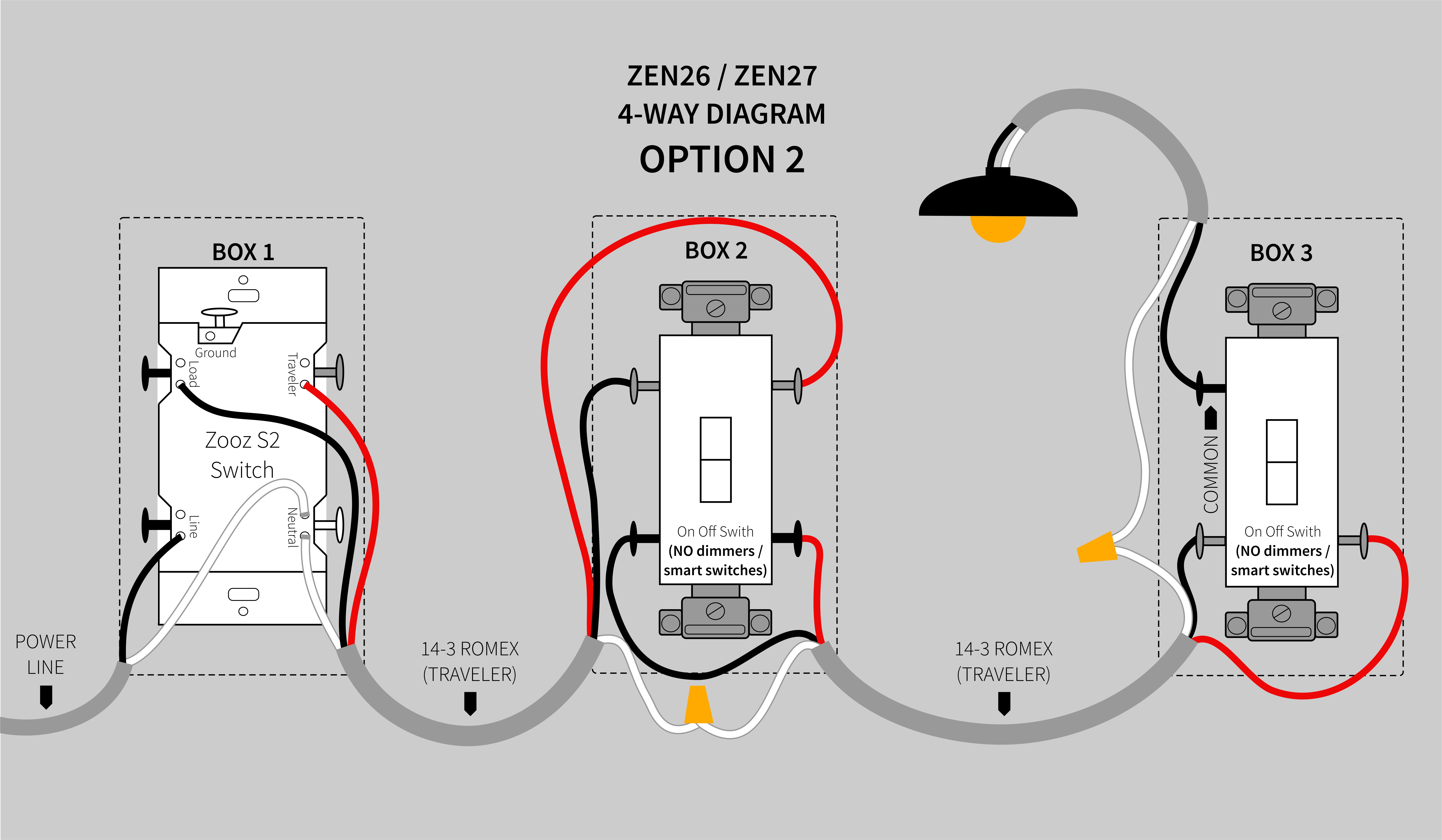
4-Way Diagrams for ZEN26 and ZEN27 S2 Switches - Zooz

4 Wire Ignition Switch Diagram | Fuse Box And Wiring Diagram

4-Way Diagrams for ZEN26 and ZEN27 Switches - Zooz Support Center
