Vt Commodore Ignition Wiring Diagram, Complete Wiring Diagrams For Holden Commodore VT, VX, VY, VZ, VE, VF, 5.36 MB, 03:54, 32,796, John Amahle, 2018-08-01T19:37:41.000000Z, 19, Vt Commodore Ignition Wiring Diagram, to-ja-to-ty-to-my-to-nasz-swiat.blogspot.com, 1272 x 1800, jpeg, bcm pcm 12j swiat nasz, 20, vt-commodore-ignition-wiring-diagram, Anime Arts
Ceramic, immersion, drytech heater or any heating source can be easily controlled by wire connected rod thermostat solutions. The rod thermostat includes temperature regulation and the option for safety integrated in a single cabinet for a most compact solution. They can be preset in a wide range of temperature according to the. One is for cool and the other is for heat, hence the abbreviation “rh” and “rc”.
Large range of parameters and options enables product customization to fit market applications as water heater, space heater, food service equipment, renewable energies and various industrial appliances. With a compact footprint, it can easily replace any controller. New user interface in short deadlines. 107 traverse des levées parc d’activité les levées 38470 vinay. Thermostat & high temp limit (eco) 1 2 1 1 2 blue connector to off peak meter (timer) tm2 4 yellow yellow 2 branch circuit to electrical distribution panel lower heating element upper thermostat & high temp. Limit (eco) upper heating element yellow black l1 junction red 1 3 1 2 black red lower thermostat 1 2 4 branch circuit to electrical distribution panel 1 upper. The thermostat controls the operation of the heater, compressor and blower as shown in figure 1. Figure 1 is a circuit diagram showing the simplest possible known thermostat control system for heating and cooling operation of an a/c and furnace or a/c and electric heat system. For this system, you will notice that g (air handler
Cotherm thermostat wiring diagram – Sweet puff glass pipe
Cotherm thermostat wiring diagram – Sweet puff glass pipe
9 Practical Cotherm Thermostat Wiring Diagram Ideas - Tone Tastic
Cotherm Thermostat Wiring Diagram

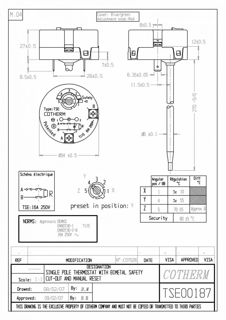
Cotherm - Replacement TSE 11" T115 16A 250V Immersion Thermostat TSE00187 - Unvented Components

TUS - WIRE CONNECTED | Cotherm

Cotherm Immersion Heater Wiring Diagram - 27
Capillary Thermostat
Untitled | DIYnot Forums
