Vt Commodore Ignition Wiring Diagram, Complete Wiring Diagrams For Holden Commodore VT, VX, VY, VZ, VE, VF, 5.36 MB, 03:54, 32,796, John Amahle, 2018-08-01T19:37:41.000000Z, 19, Vt Commodore Ignition Wiring Diagram, to-ja-to-ty-to-my-to-nasz-swiat.blogspot.com, 1272 x 1800, jpeg, bcm pcm 12j swiat nasz, 20, vt-commodore-ignition-wiring-diagram, Anime Arts
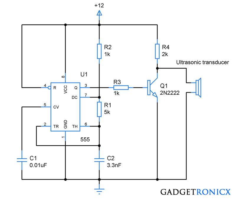
The ultrasonic generator is specially matched to a specific transducer load hence generators and transducers are to be replaced only with the same types. 3. 2 function the ultrasonic system is generally consisting of an ultrasonic generator, a transducer and a cleaning bath with the cleaning liquid intended for a desired Schematic of a typical ultrasonic cleaner. For those on the trail of the diy ultrasonic cleaner this schematic is a good place to start.
A power transistor along with its supporting components. Exmark diagram parts lazer deck 48 wiring series 2009 pontoon boat muttonpower. Call crest technical support for assistance at: The ultrasonic cleaning process ultrasonic energy placed in liquid causes alternating patterns of low and high pressure phases. During the low pressure phases, minute bubbles form. During the subsequent high pressure phases, the bubbles implode violently. This process is called cavitation. Cavitation provides an intense scrubbing action that. Crest ultrasonic wiring diagram.
Ultrasonic Cleaner Wiring Diagram

Ultrasonic Cleaner Wiring Diagram

Ultrasonic Cleaner Wiring Diagram

Ultrasonic Equipment
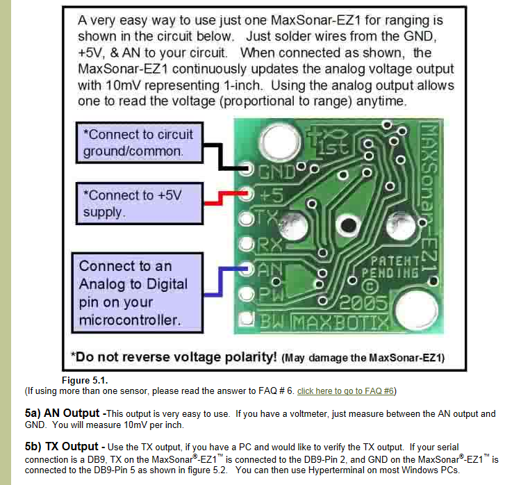
Wiring Maxbotix ultrasonic sensor to serial on cRIO? - Electrical - Chief Delphi

Optimum Console Junior | Crest Ultrasonics

Ultrasonic Electrostatic Transducer for Ultrasonic Measurement ~ Transducer Circuit Diagram

Ultrasonic Cleaner Wiring Diagram

Pin on electronics

Ultrasonic Cleaner Wiring Diagram
