Vt Commodore Ignition Wiring Diagram, Complete Wiring Diagrams For Holden Commodore VT, VX, VY, VZ, VE, VF, 5.36 MB, 03:54, 32,796, John Amahle, 2018-08-01T19:37:41.000000Z, 19, Vt Commodore Ignition Wiring Diagram, to-ja-to-ty-to-my-to-nasz-swiat.blogspot.com, 1272 x 1800, jpeg, bcm pcm 12j swiat nasz, 20, vt-commodore-ignition-wiring-diagram, Anime Arts
Shunt trip breaker wiring diagram symbol coil explanation device circuit. Svg shunt diagram current side file wikimedia commons pixels. If a display module relay is being installed instead of a bell alarm, connect lead wires to #4 and #22 holes respectively. ) 4) route bell alarm lead wires rt9 through. This installs on the main breaker to add.
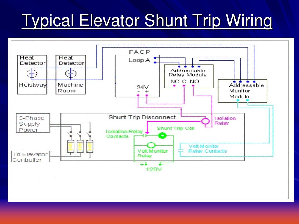
Please look at the above shunt trip breaker wiring diagram. Let’s discuss the connection procedure: At first we have to connect the neutral wire of the power supply to anyone terminal of the shunt trip coil. If its terminals are identified. Add a 120v dedicated ckt for shunt trip control wiring. The shunt doesn't draw much so a 15 amp will do. The fire alarm contractor should supply a set of normally open contacts controlled by the fire alarm panel. Send 2 conductors from here to the shunt trip device. You have now put a single pole switch in line with the load ie the shut trip breaker.
Elevator Shunt Trip Requirements and Codes | Fire Alarms Online

Elevator Shunt Trip Breaker Wiring Diagram
shunt trip breaker wiring diagram - Wiring Diagram

Elevator Shunt Trip Wiring Diagram - Free Wiring Diagram
Elevator Shunt Trip Breaker Wiring Diagram - Wiring Diagram

How to Wire Elevator Shunt Trip | Fire Alarms Online

Elevator Shunt Trip Wiring Diagram - Free Diagram For Student

Shunt Trip Wiring Diagram For Elevator - Wiring Diagram

30 Elevator Shunt Trip Wiring Diagram - Wiring Diagram Database
Elevator Shunt Trip Breaker Wiring Diagram
